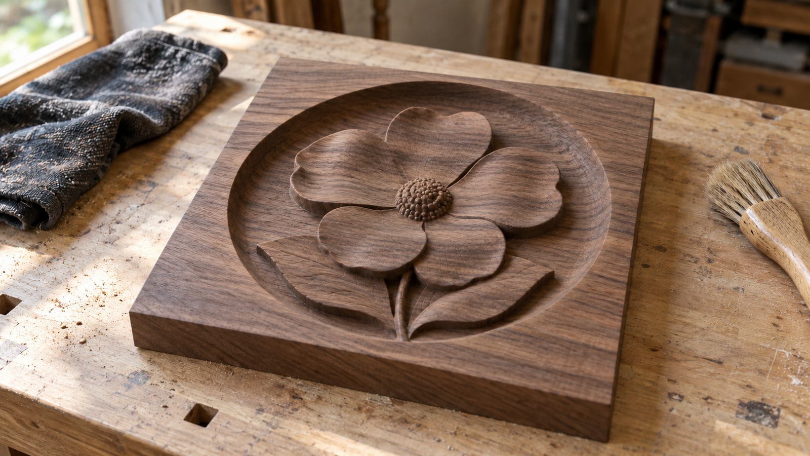
The design is ready, the walnut is cut, and the CAM software is asking for something you did not expect. Not one toolpath. Two. One called roughing, one called finishing, each wanting a different bit, a different stepover, and a number labelled machining allowance that you have never had to set before. Underneath all that, the workpiece is a circle, and every clamp you own is designed to grip a straight edge.
That is where a first relief carve stalls. Not on the artwork, and not on the machine, but on a handful of setup decisions that nobody explains because they seem obvious once you know them.
Tip
Short answer: roughing and finishing usually split bulk removal from detail work. Some shallow jobs need fewer operations. Rough with a larger bit and leave a thin allowance, finish with a small ball nose at a fine stepover. Hold a round blank by carving it on square stock and cutting the circle out last, in the same setup.
What you are actually feeding the machine
A 3D relief carve is driven by height data: a greyscale depth map, or a 3D model. What a depth map is and how brightness becomes height is covered in full elsewhere, so this post assumes you already have one loaded and scaled in your CAM software.
Worth being blunt about one thing before you go looking. Our relief medallion packs are SVG line art. The sculpted appearance is drawn, using directional hatching that follows the form and a cast shadow that lifts the subject off the background, and there is no height data anywhere in the file. Load one into a 3D toolpath and there is nothing for it to read.
So the height data comes from somewhere else. Either you buy or paint a depth map, or you generate one. Craftgineer's ReliefMaker builds a carving-ready greyscale map from an illustration in the browser, free with its local AI mode and with an optional paid mode, like every Craftgineer tool behind a free account. Craftgineer is our sister site, so treat that as a recommendation with an interest attached.
The other honest route on a router is to skip depth maps entirely and V-carve the linework. A V-bit cuts deeper where the stroke is wider, so the hatching that draws the relief becomes real physical grooves with real shadow. It is a fraction of the machine time and it suits the medallion files as drawn. Our V-carving tutorial covers that path.
 North American Wilderness Relief Medallions30 designs, commercial license included$3.99
Either way, pick a subject that agrees with a circle before you commit an expensive blank to it. A head study fills a round on its own; a leaping fish leaves two bald crescents unless the design brings its own border. There is a whole post on choosing a relief design for a round blank if that decision is still open.
Workholding, which is the problem you should solve first
A circle has no flat to clamp and no corner to register against. Inadequate restraint at the rim can let cutting forces rotate it, and a workpiece that rotates mid-carve is scrap in a way that a workpiece that lifts is not, because the damage looks like a design decision until you look closely.
There are three sane answers, in order of how much grief they save.
Carve square, cut round last. Start with rectangular stock, clamp it normally at the corners, run the relief, and then finish with a profile toolpath that cuts the circle out with a few tabs holding it in. The stock never has to be round while the machine is working on it, and the circle ends up perfectly concentric with the carving because both came from the same origin. This is the answer for almost every first medallion.
Fasten a ready-made round to a carrier board. If the blank is already a wood round, screw a piece of flat scrap plywood to your spoilboard and mount the blank to that. One option is fastening from beneath the carrier, after checking screw length against the remaining material under every toolpath. Keep both screw tips and heads outside the cutter’s swept volume. A tested tape-and-adhesive setup may suit some jobs, but holding force depends on surface preparation, bonding area and cutting loads.
Machine a nest. Pocket a shallow circular recess into the carrier board, the same diameter as the blank plus a hair, and drop the blank into it. Because the machine cut the nest, the nest is concentric with the machine's own coordinates, which means you can reload an identical blank later and it lands in exactly the same place. The nest locates the part; it does not by itself prevent a circular blank from spinning or lifting. Add suitable restraint and confirm the fixture and work offsets for every reload.
Whichever you use, get the surface flat and get Z zero right. A relief carve references every height in the file to your Z zero, so an error there shifts the entire carving deeper or shallower than intended, and on a shallow relief that can mean the highlights never get touched at all. If the blank is cupped or the carrier is not flat, surface it with a facing pass before you start.
One more thing that only bites once. Leave the workholding alone from the first toolpath to the last. Roughing and finishing share an origin, and if the stock moves between them the finishing pass carves a shifted copy of the same surface over the top of the first one.
Why two toolpaths, and what each one is for
This is the part that makes the rest make sense. The operations split the work for efficiency and controlled tool engagement.
A large bit removes material fast. Its diameter, its rigidity, and the depth it can take per pass all favour volume. What it cannot do is reach into any concave detail smaller than its own radius. Run a quarter inch ball nose over an elk's eye socket and the socket comes out as a soft dish, because the tool physically will not fit into the shape.
A small ball nose reaches that detail. What it cannot do is clear a cubic inch of waste in a sensible amount of time, because everything that makes it fine also makes it slow and fragile.
So the work gets split.
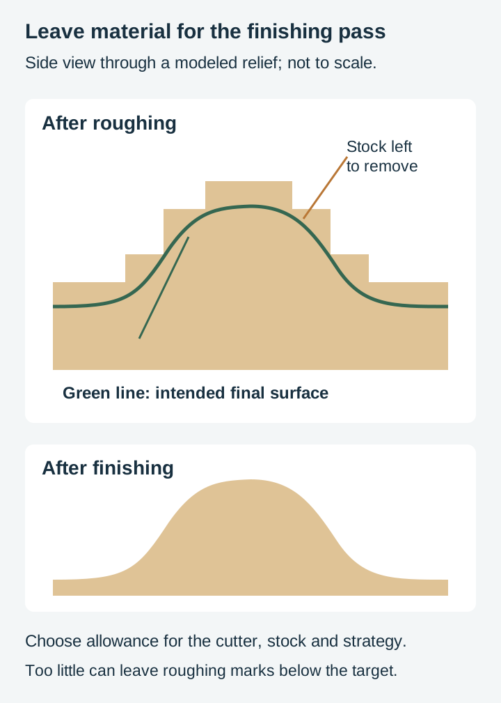
The roughing pass removes the bulk. It usually runs as a series of flat levels, each one clearing everything above a given height, stepping down through the material until it reaches the deepest point of the relief. It is not trying to make the surface look like anything. It is trying to get most of the wood out of the way.
The machining allowance is the number that connects the two. It tells the roughing pass to stop short and leave a thin skin of material everywhere, so the finishing pass always has something to cut. Vectric's documentation calls it exactly that, a machining allowance, and describes it as material left on for the finish pass to remove. Other packages call it stock to leave.
Too little allowance can leave roughing marks or damage that the finishing pass cannot remove. Leave too much and the finishing pass is doing volume removal with a tool chosen for detail, which is slow and hard on the cutter. Choose an allowance appropriate to the tools, material and roughing quality, then inspect the simulation.
The finishing pass is the one people mean when they talk about a 3D carve. A ball nose walks the entire surface in closely spaced lines, rising and falling to follow the height data. It is where the hours go, while stock movement or damage during roughing can still affect the result.
Stepover, and the geometry behind a smooth surface
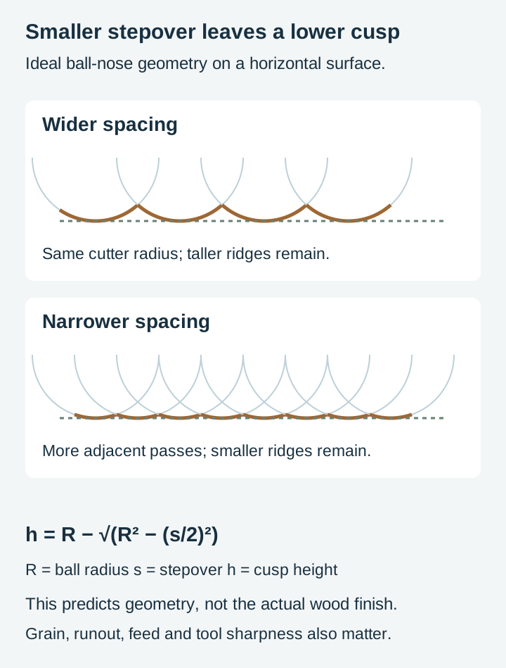
Stepover is how far the ball nose shifts sideways between one pass and the next. It strongly affects the geometric scallop pattern. Surface slope, runout, deflection, grain, tool sharpness and cutting conditions also affect the finished surface.
A ball nose is a hemisphere. Two overlapping passes leave a small ridge of uncut material between them, called a scallop or a cusp. For parallel passes over an ideal horizontal surface, its height follows the tool radius and stepover:
scallop height = r - sqrt(r² - (stepover / 2)²)
For a 1/8 inch ball nose, which is 3.175 mm across, that works out as follows. These are calculated from the formula above, not measured on a machine, and they describe the ridge left by the tool geometry alone, before any real world runout or deflection.
| Stepover, as percent of tool diameter | Stepover in mm | Scallop height |
|---|---|---|
| 10% | 0.32 mm | 0.008 mm |
| 15% | 0.48 mm | 0.018 mm |
| 20% | 0.64 mm | 0.032 mm |
| 30% | 0.95 mm | 0.073 mm |
| 40% | 1.27 mm | 0.133 mm |
| 50% | 1.59 mm | 0.213 mm |
Two things fall out of that table, and they are the whole argument.
Scallop height grows roughly with the square of stepover. Doubling from 10 percent to 20 percent makes the ridges four times taller. Going from 20 to 40 quadruples them again.
Raster time generally grows as stepover decreases. Halve the stepover and the tool has twice as many lines to walk, so the pass takes about twice as long.
Put those together and the trade is clear. Halving your stepover roughly doubles the runtime and reduces the ridges by about four times. That is why fine stepovers are worth it up to a point and pointless past it: once the scallops are smaller than the fuzz on the wood, you are buying machine hours and getting nothing you can see or feel.
The practical target is a scallop you can sand off in a few minutes without losing detail. At the coarse end you are sanding away the modelling you paid the hours for, since a fifth of a millimetre of ridge is deeper than a lot of the fine texture in a good relief. Use the calculated range to compare options, then choose a starting stepover with the tool and machine guidance. The table is not a universal default or a prediction for every sloped surface.
Two related settings sit next to it. Raster angle decides the direction the lines run, and changing direction relative to the grain can alter the visible texture; compare the result on a sample. Some people run a second finishing pass at 90 degrees to the first, which costs another full pass and produces a noticeably cleaner surface on figured wood. Boundary offset decides how far outside the model the pass extends, and setting it too tight leaves an unmachined lip around the edge of the relief.
Bits, and the case for a tapered ball nose
For a first carve, a quarter inch bit for roughing and an eighth inch ball nose for finishing covers the majority of medallion-sized work. The CNC router SVG guide has a broader rundown of bit types if you are still building a set.
The one upgrade worth knowing about early is a tapered ball nose. A straight 1/8 inch ball nose that has to reach 15 mm into a deep relief is a long, slender rod, and slender rods deflect and chatter. A tapered bit has the same small ball at the tip but the shank widens as it goes up, so it is far more rigid at the same reach. That means it holds fine detail at depths where a straight bit would wander.
The tradeoff is the taper itself. On steep walls the widening body can contact the material before the tip has finished cutting, so very deep vertical detail is not its strength. For the rounded, modelled forms that make up most relief work, it can be a useful tool, provided the CAM definition includes the actual tip and taper.
Keep it sharp, whichever you use. A dull ball nose tears rather than shears, and it does its tearing on the finishing pass, which is the one pass where damage is permanent.
The sequence, start to finish
- Prepare the carrier. Screw flat scrap to the spoilboard and surface it, so the top of the carrier is parallel to the machine rather than to the floor.
- Mount the stock. Square stock clamped at the corners, or a round blank screwed or taped to the carrier, keeping all fasteners outside the area the cutter will visit.
- Set the job to real dimensions. Enter the actual stock thickness, and decide deliberately whether Z zero is the top surface or the machine bed. Stay consistent with how you will probe.
- Import and scale the depth map, keeping the aspect ratio, and set the depth range for the deepest point. Shallower is the safer first choice.
- Create the roughing toolpath. Larger bit, level-based clearing, and a machining allowance left on for the finish.
- Create the finishing toolpath. Small ball nose, a stepover in the low tens of a percent of tool diameter, and a raster angle running across the grain.
- Add the profile toolpath last if you are cutting a circle from square stock, with enough tabs to hold the piece when it breaks free.
- Simulate all of it. Watch the preview through to the end. It is free, it takes a minute, and it catches an inverted map, a background that did not clear, or a carve that goes deeper than your material long before the machine does.
- Check the time estimate and compare it with the required detail. A long runtime is a reason to review the strategy, not proof that the stepover is wrong.
- Zero X, Y and Z, then run the roughing pass.
- Account for the new tool length. On a manual setup, re-establish Z using the same reference; an equipped machine may handle this through tool-length offsets. Keep the established X/Y work offsets and the workholding unchanged.
- Run the finishing pass and watch the first few minutes. If the Z re-zero was wrong, the opening plunge tells you immediately, and that is the moment to hit stop.
- Cut the profile, release the piece, and clean up the tabs with a flush trim or a chisel.
The step people skip is number 11, and it is the one that ruins finished carves. A confident re-zero of X and Y after a tool change puts the finishing pass a millimetre off, and a millimetre is more than the entire depth of the detail on most reliefs.
Feeds, speeds, and why there is no table here
We do not own a CNC router, so any feed rate or spindle speed printed here would be a guess wearing a lab coat. Bad numbers in this area break tooling and start fires, which is a good reason to send you to sources that actually measured them.
Bit manufacturers such as Amana Tool, Whiteside, and Onsrud publish chip load and feed recommendations for their own cutters by material. Your machine's maker publishes starting parameters that account for the rigidity of your particular frame. Vectric ships an editable tool database with starting values, and Carbide Create ships defaults tuned for Shapeoko machines. Start from whichever of those matches your hardware and adjust from there.
What is safe to say generally is what each setting is doing to the cut. Depth per pass on the roughing toolpath is limited by how much load your machine can take without deflecting, which is why a rigid steel frame and a hobby gantry get different numbers from the same bit. Feed rate and spindle speed together set the chip thickness, and chips that are too thin let the cutter rub and heat instead of cut, which dulls it fast. Finishing engagement should be controlled, but feed, speed, allowance and local slope still matter along with stepover.
When it goes wrong
Visible terracing on smooth curves. Check depth-map quantization, model resolution, toolpath tolerance and stepover. An 8-bit map spread over a deep carve has coarse steps in it.
Stripes across the surface following the grain. Scallops lining up with the grain direction. Change the raster angle or add a crossing pass.
Detail comes out mushy. The finishing bit could not fit into the shapes. A smaller ball nose or a larger carving are the two fixes, and enlarging the carving is usually cheaper.
A gouge where finishing starts. Check tool length, Z reference, entry moves, remaining stock and workholding.
The whole carve is offset from the roughing. X or Y moved, either at the control or because the stock shifted.
Fuzzy raised edges. Softwood and open grain fuzz on delicate raised forms whatever you do. Tight-grained hardwoods hold this kind of detail far better, which is why walnut, maple, and cherry dominate relief work.
Tearout as the profile pass breaks through. Too few tabs, or a climb versus conventional direction issue on the final cut.
Finishing the surface without erasing it
Remove loose dust with suitable extraction and a soft brush. Test any abrasive brush on scrap before using it on fine relief details.
Sand by hand and lightly, 220 grit or finer, and only on the raised surfaces. A power sander rounds every crisp edge the finishing pass produced, which on a relief is most of what you were paying for.
A coat of sanding sealer before the final sanding stiffens the loose fibres so they cut rather than lie down, which makes a real difference on anything less dense than maple. After that, oil finishes suit relief work because they soak in rather than pooling in the recesses the way a thick film finish does.
Pick a subject and start small
A modest maple test panel lets you learn allowance, stepover and tool changes before committing a larger blank. Estimate the runtime for your actual model and machine. Get one off the machine before you commit a slab of figured walnut to a two foot carve.
 European Wildlife Relief Medallions30 designs, commercial license included$3.99
 Big Cat Relief Medallions50 designs, commercial license included$3.99
If the V-carved route is where you want to start, and for a first router project it is a reasonable place to begin, every pack is $3.99, ships as SVG, PNG, JPG, PDF, and EPS, and includes a commercial license covering unlimited physical products, including print-on-demand. Browse the medallion designs in Wildlife, Big Cats, and Sea Life, or the full catalog.
Designs for this project
Frequently Asked Questions
Why does a relief carve need two toolpaths?
Roughing and finishing often use different tools for efficiency. A shallow job may use one tool or omit separate roughing if engagement remains suitable. A large bit removes the bulk of the waste quickly but cannot reach concave details that do not admit its cutting profile. A small ball nose reaches the detail but would take an unreasonable amount of time clearing waste. So the roughing pass removes volume with a bigger cutter and deliberately leaves a thin skin of material, and the finishing pass walks that skin off with a small ball nose to produce the surface you actually see.
What stepover should I use for a finishing pass?
Stepover sets how far the ball nose shifts sideways between passes, and the ridges left between passes shrink roughly with the square of it while raster cutting time generally grows as stepover gets smaller. Halving your stepover roughly doubles the runtime and cuts the ridge height by about four times. Most CAM packages default to somewhere between 10 and 20 percent of the tool diameter for finishing, and that default is the sensible place to start.
How do I hold a round blank on a CNC router?
The easiest answer is not to. Carve the relief on square stock and cut the circle out last with a profile toolpath and tabs, all in the same setup. If the blank is already round, fasten it to a flat carrier board with screws driven from underneath, or with the painter's tape and superglue method, and screw the carrier to your spoilboard. A circular nest locates the blank but still needs restraint against lifting and rotation.
Do relief medallion SVG files carve real 3D depth?
Not by themselves. Our relief medallions are vector line art, so the sculpted look is drawn with hatching rather than stored as height data. Physical 3D depth comes from a greyscale depth map or a 3D model, which is a separate file you supply or generate. A router can still V-carve the linework for real depth in the lines, which is a different look and a much faster job.