The design opened fine everywhere else. Then you dropped it into CAM, or into the software that came with a cutter you have owned for eight years, and it either refused the file outright or brought it in as something unrecognisable: a part the size of a dinner plate when you drew a coaster, or a curve with flat spots you can count.
DXF is where a lot of otherwise clean files go wrong, and it goes wrong quietly. The conversion succeeds, the preview looks right, and the damage only shows up in the finished piece. Our packs ship as SVG, PNG, JPG, PDF, and EPS, so if something in your chain wants DXF you are making it yourself, which means you are also the one who has to check it.
Tip
Short answer: export DXF only when a program genuinely refuses SVG. Set the export units to match what the receiving software expects, then check three things before you cut: the size of a known dimension, whether the curves came through as curves, and whether closed shapes are still closed.
First, work out whether you need DXF at all
Plenty of people convert out of habit and inherit problems they did not need. Almost every piece of modern craft and hobby CAM software reads SVG natively now, including LightBurn, the Glowforge app, xTool Creative Space, Cricut Design Space, Carbide Create, Easel, and Vectric's VCarve line. If you are using one of those, open the SVG and stop reading this section.
The cases where DXF genuinely earns its place are narrower:
- CAD-first CAM. Sketch import in a mechanical CAD package is usually built around DXF, and its SVG support ranges from limited to absent depending on version.
- Silhouette Studio Basic Edition. The free tier does not open SVG, but it has long accepted DXF. Silhouette's own documentation is the place to confirm what your version takes.
- Vinyl plotter software from the CorelDRAW era. Cutter drivers written in the 1990s and early 2000s predate SVG entirely.
- Job shops. Send a design out to a laser cutting, waterjet, or sheet metal service and DXF is frequently what the quoting system expects.
If none of those describes your setup, the honest answer is to skip the conversion. Our file format decision guide covers which file to reach for in every common craft workflow, and DXF is rarely the winner.
What DXF carries, and what it leaves behind
DXF is a CAD interchange format. It was designed to move engineering geometry between programs, not to move artwork, and that difference explains most of the surprises. The table describes common outline-export behavior. DXF itself supports more features than many craft exporters preserve.
| Thing in your SVG | What happens in DXF |
|---|---|
| Path outlines | Survive, as line, arc, polyline, or spline entities |
| Fills and solid black shapes | Often exported as boundaries; DXF also supports filled HATCH and SOLID entities |
| Stroke widths | Often exported as centerlines; DXF has width and lineweight features, but mapping varies |
| Colours | May become indexed layer colors; newer DXF also supports true color |
| Layers | Survive, though older revisions restrict the names |
| Text | May be outlined, omitted or exported as font-dependent text; outline it first |
| Gradients, transparency, blur | Do not expect SVG appearance to survive an outline export |
| Clips and masks | Not reliably applied. The full uncropped shape can reappear |
The fills line is the one that catches designers out. With an outline exporter, a filled silhouette typically arrives as its boundary. That is fine for cutting, because a cutter follows boundaries anyway, and it is a real problem if you were counting on the fill to tell you which regions get engraved. Assign that by layer instead.
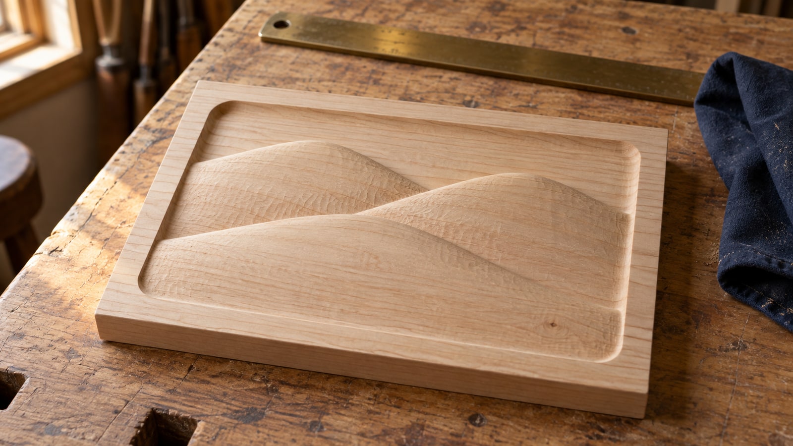
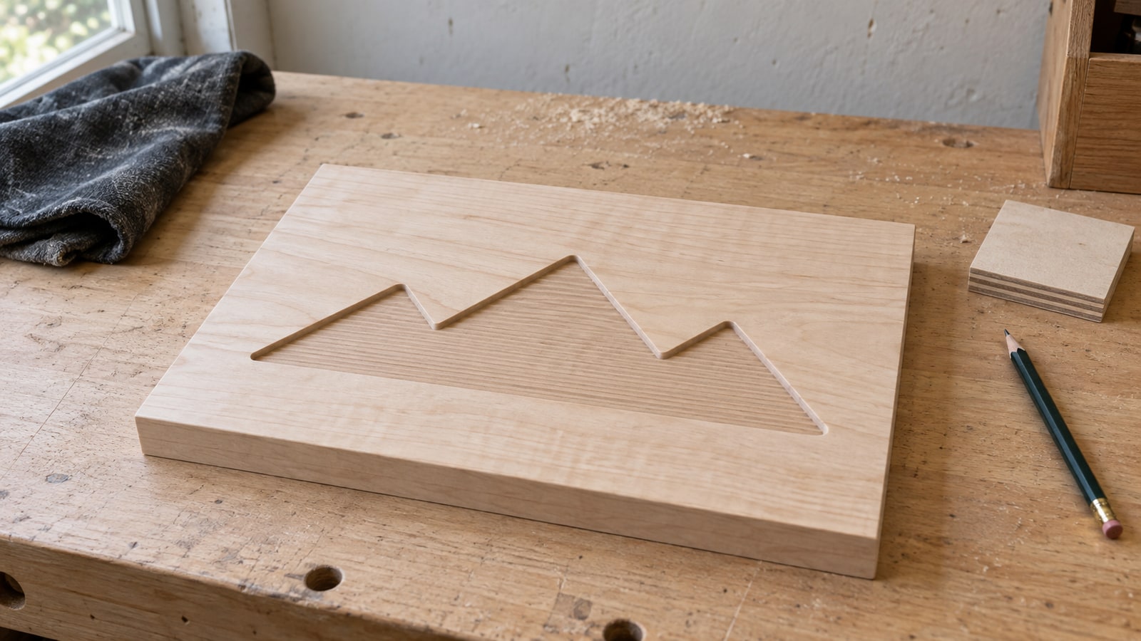
A design like our mountain sign artwork is a good example of a file that converts well, because it was drawn as clean closed outlines with long sweeping ridgelines rather than as a filled painting. The geometry is the whole design, so there is nothing for the conversion to throw away.
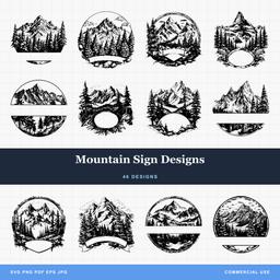 Mountain Sign Designs46 designs, commercial license included$3.99
Three things to fix in the SVG before you export
Do this in Inkscape on a copy, not on your master file.
Convert every piece of text to paths. Select the text and use Path then Object to Path (Shift+Ctrl+C). A DXF text entity carries a font name, and if the receiving computer lacks that font it substitutes something else, which changes the letter shapes and often the overall width. Outlined text has no such dependency and cuts identically everywhere.
Decide what your strokes are supposed to be. A common outline exporter follows the SVG stroke’s centerline instead of reproducing its visible width. If the line is a cut path, leave it alone and the centreline is exactly what you want. If the stroke is the visible artwork, for instance a chunky hand drawn outline you intend to cut out as a shape, run Path then Stroke to Path first so the outline becomes a real closed contour.
Name your layers something a 1990s parser would accept. Older DXF revisions were fussy about layer names, disliking spaces and lowercase in various combinations. Short uppercase names like CUT, POCKET, and ENGRAVE travel everywhere without argument, and they map straight onto operations once the file lands in CAM.
While you are in there, release any clips or masks and redo that trimming with real boolean operations. The exporter is not obliged to honour a clip, and a shape you thought you had cropped can arrive at full size.
Exporting DXF from Inkscape
Inkscape is free, it is the tool most crafters already have, and its DXF export is good enough for cut work once you know which boxes to tick.
-
Set your document up in real units. File then Document Properties, and set the display unit to millimetres or inches. Then select your design and read its width in the toolbar. Write that number down, because it is what you will verify after import.
-
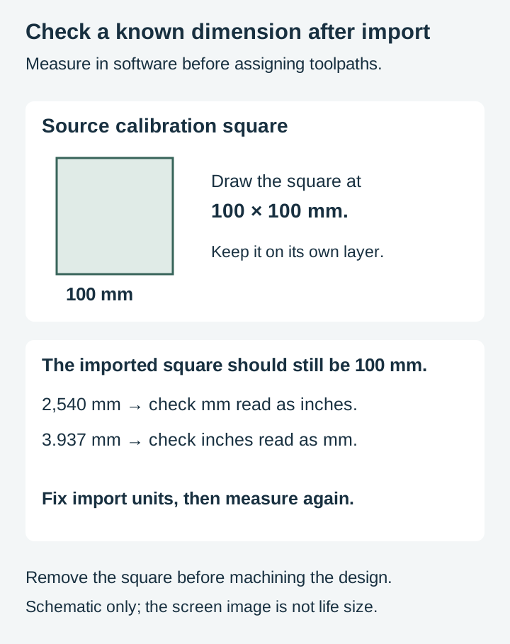
Add a calibration square. Draw a rectangle exactly 100 mm by 100 mm, or 4 inches by 4 inches if you work in imperial, and put it on its own layer named CALIBRATION. It costs nothing and it turns a scale problem from a mystery into a two second measurement.
-
Use Save a Copy, not Save As. Shift+Ctrl+Alt+S keeps your SVG master intact and open. Save As would leave you editing a DXF, which is not a format you want to keep working in.
-
Choose the DXF format. In recent versions it is listed as Desktop Cutting Plotter (AutoCAD DXF R14). The exact wording drifts between releases, so look for DXF in the format dropdown rather than matching the string.
-
Set the base unit in the options dialog. This is the single most important setting on the screen, and it is the one people click past. It tells the exporter what one unit in the file means. Match it to what the receiving software expects.
-
Leave the ROBO-Master spline option alone unless you know you need it. It emits spline output aimed at one specific plotter package, and other programs frequently cannot read it. Turning it on hopefully, in the belief that splines are always better, is a common way to end up with a file nothing will open.
-
Choose which layers to export. The dialog can send everything, visible layers only, or layers matching a name. Visible only is the tidy option if your working file has reference material parked on hidden layers.
-
Save, then immediately open the result. Not later, not at the machine. Now, while the source file is still in front of you.
Scale is the failure that ruins the most parts
Here is the uncomfortable truth about the format: a DXF is full of numbers, and those numbers do not have to mean anything in particular. The format has a header variable for units, it is allowed to hold a value meaning unitless, and a fair number of exporters write exactly that. The receiving program then falls back on its own default, which may not be yours.
So a coordinate of 100 in the file might be 100 millimetres, 100 inches, or 100 of whatever the CAM decided. Nothing is corrupt. Nothing errors. Your sign is just eight feet wide.
The ratio between the expected and imported dimensions can suggest a unit mismatch:
| Your part is off by | Check for |
|---|---|
| 25.4 times too big | Millimetres read as inches |
| 25.4 times too small | Inches read as millimetres |
| About 3.78 times too big | SVG pixel numbers read as millimetres |
| 96 times too big | SVG pixel numbers read as inches |
| About 6–7 percent off | A possible historical 90/96-dpi mismatch |
That last row has a specific cause worth knowing. Inkscape moved its internal resolution from 90 to 96 dots per inch in version 0.92, documented in that release's own notes, and a file authored before the change can land about six percent away from its intended physical size. If your part is close but not right, and no unit swap explains it, an old source file is one possibility, not a diagnosis.
The fix for all of it is the same and it is boring: import the DXF, measure the calibration square with the CAM's measuring tool, and confirm it reads 100 mm. If it does not, set the import units correctly and measure again rather than scaling the geometry by hand to make the numbers work. Scaling to compensate hides the problem and it will come back on the next file. Once the square measures right, delete it and carry on.
Curves are the failure you cannot see on screen
This is the part that deserves saying precisely rather than dramatically, because there is a lot of confident nonsense about it online.
DXF is perfectly capable of describing curves. It has ARC, CIRCLE, ELLIPSE, and SPLINE entities, and a spline is a real mathematical curve in the same sense a Bezier is. Anyone telling you DXF cannot do curves is wrong.
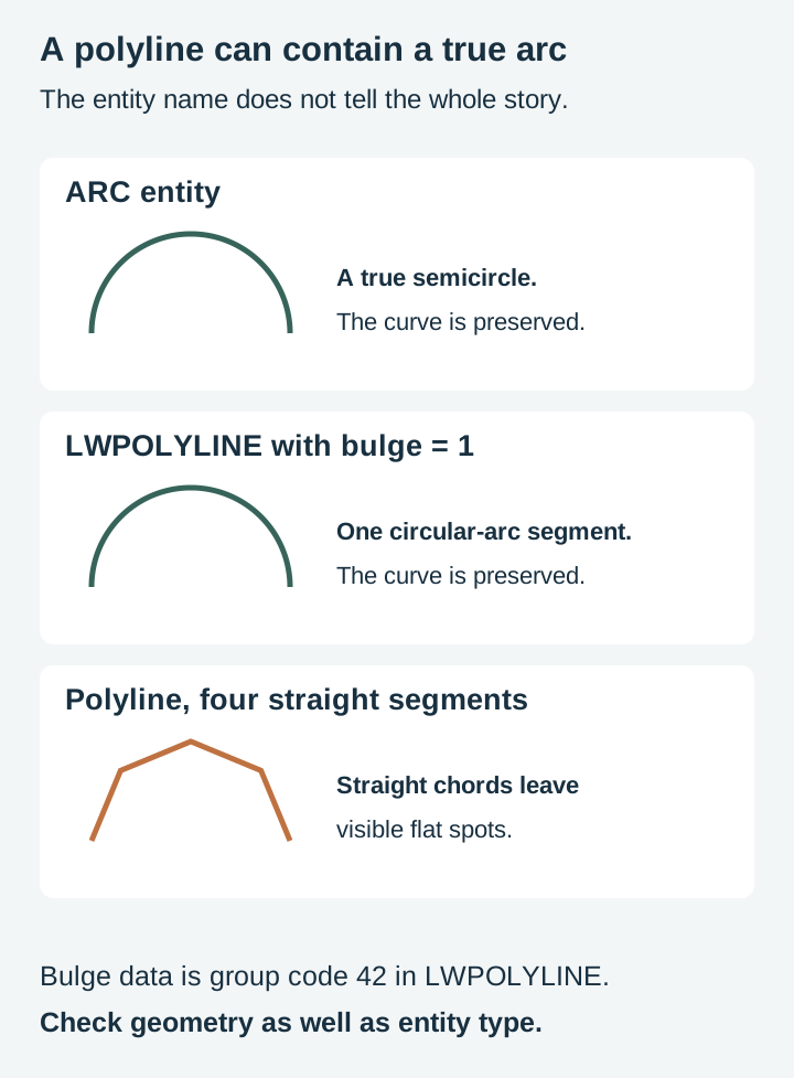
What is true is that many exporters do not use those entities. Faced with a Bezier curve, an exporter can either translate it into a spline or approximate it with a polyline made of short straight segments. Some exporters flatten curves, while others retain splines or fit circular arcs. Inkscape’s R14 exporter can emit SPLINE entities as well as polylines; do not assume that its polyline option turns every curve into straight segments. Inspect the actual output and the receiving program’s interpretation.
A coarse approximation may show facets in the finished piece even when the normal-size screen preview hides them. Watch especially for these situations:
- You scale the design up after export. The segments scale with it, and flat spots that were invisible at four inches are obvious at fourteen.
- The flattening tolerance was coarse to begin with. Some exporters trade fidelity for a smaller file, and the trade is not always in your favour.
- The tool is small and the material shows everything. A fine V bit in hardwood or a laser on acrylic edges will reproduce every vertex faithfully.
The counterweight is worth stating too, because "polylines are bad" is not a rule. If the segments are short relative to your tool diameter and your material's finish, a flattened curve cuts identically to a true one. Plenty of production work runs on flattened geometry with nobody able to tell. The problem is not flattening, it is flattening you did not know about and cannot account for.
Which is why you check.
How to spot a degraded curve before you cut
Inspect entity types and segment data. ASCII DXF opens in a text editor; binary DXF requires a compatible reader or an ASCII re-export. Look for SPLINE, ARC, CIRCLE and ELLIPSE. A LWPOLYLINE can also contain real circular arcs: a nonzero bulge value, group code 42, defines an arc segment. Polyline presence alone does not prove straight-line flattening. Autodesk’s LWPOLYLINE reference documents that distinction.
Use file size as a clue. Unexpected growth warrants inspection, but file size alone does not identify flattened curves or poor geometry.
Inspect a curve in CAM. Check its entity type, segments and deviation from the original. A complex spline can have many control points, and one polyline can contain either arcs or straight segments.
Zoom properly, then zoom more. Take a curve to a magnification where an inch on screen is a millimetre on the part. Flat spots that hid at fit-to-window become plainly visible, though be aware that some editors render curves coarsely at low zoom to stay responsive, so a chunky look at 100 percent proves nothing on its own.
If you do find flattening and it matters, the two practical responses are to export at final size so nothing gets scaled afterwards, and to look for an arc fitting or curve tolerance option on your CAM's import dialog, since many packages will refit polylines into arcs on the way in. Our guide to node bloat and faceted curves goes further into how to tell a true curve from a polyline in an editor and how to refit one that has already been damaged.
Open paths and orphan geometry
The other thing a DXF round trip does is fragment shapes. A single closed path in the SVG can arrive as a set of separate line and arc entities that merely touch end to end, each one technically open, each endpoint rounded to whatever precision the exporter used.
CAM cares about this a great deal. Area pocketing and many V-carve operations require closed boundaries. Profile tools can also follow open vectors on a selected side, so closure requirements depend on the operation. Some software silently skips those contours, which is how a design comes off the machine with three of its five shapes carved.
Every serious CAM package ships a join tool with a tolerance setting precisely because DXF made it necessary. Run it after import, start with a small tolerance so you do not weld separate shapes together, and check that your closed shapes now report as closed. The full walkthrough of what open paths do and how to find them lives in our open path troubleshooting guide.
While you are looking, check for geometry that should not exist: duplicate contours stacked exactly on top of one another, stray fragments far outside the artwork, and construction lines you forgot were on a hidden layer. Select all and look at the overall bounding box. If it extends past your design, something is out there.
Two minutes before you press start
Run this every time and DXF stops being scary.
- Measure the calibration square. It reads 100 mm or it does not.
- Delete the calibration square.
- Inspect a curve’s entity type, segments and any polyline bulges.
- Zoom hard on the smoothest curve in the design.
- Run the join tool, then confirm your closed shapes report as closed.
- Check the bounding box for anything living outside the artwork.
- Preview the toolpath and watch where the tool actually travels.
Then run the job in air over the material before you commit, which is standard practice for a reason and costs you nothing but time.
When Inkscape is not the right exporter
Inkscape's DXF export is serviceable and free, and it is not the only option. If it produces something your software chokes on, the usual suspects are the DXF revision it writes and the spline handling, neither of which Inkscape gives you much control over.
Craftgineer's File Converter is worth a try in that situation. Craftgineer is our sister site, so treat the recommendation with the appropriate pinch of salt, but the tool is genuinely free and it converts between SVG, DXF, PDF, PNG, and STL in the browser. Like every tool over there it needs a free account, so sign in first. Running the same SVG through a second exporter and comparing the two DXFs in a text editor is a fast way to find out whether your problem is the file or the exporter.
Other routes exist too. LibreCAD and QCAD open and re-save DXF at different revisions, and any vector editor with a DXF export gives you another set of defaults to compare against. The general principle holds regardless of which one you use: convert once, from the SVG, at final size, and check the result rather than trusting it.
Start from a file that is worth converting
Every conversion is a lossy negotiation, and the quality of what comes out the far side is capped by what went in. A design drawn as clean closed vector paths, with curves that are actually curves and no leftover geometry hiding under the artwork, gives an exporter something straightforward to translate. A file auto traced from a JPEG gives it forty thousand noisy vertices and no chance.
That is the half of the problem you control before you ever open the export dialog. Our packs are drawn as vectors from the first stroke, which gives the exporter defined geometry to translate. Still check scale, curves, closure and assigned operations after conversion.
Mountain Sign Designs46 designs, commercial license included$3.99 Trees Design Pack81 designs, commercial license included$3.99
Both of those are built for exactly the kind of sign and panel work that tends to end up in CAM, at $3.99 with the commercial license included, and files delivered as SVG, PNG, JPG, PDF, and EPS. Browse the rest of the nature and outdoors collection or the full catalog, open the SVG, and only make a DXF when something actually asks for one.
Designs for this project
Frequently Asked Questions
Can I convert SVG to DXF for free?
Yes. Inkscape is free and exports DXF from its Save a Copy dialog. Craftgineer's File Converter does the same in a browser, free with a free account, and it also handles PDF, PNG, and STL. There is no reason to pay for this conversion.
Why did my DXF come in at the wrong size?
DXF numbers are unitless unless the exporter writes a units code into the header, and plenty of exporters do not. The receiving program then applies its own default. If your part is 25.4 times off you have a millimetre and inch mismatch, and if it is about 3.8 times off you exported pixel numbers into a millimetre document.
Does DXF support curves, or does everything become straight lines?
DXF supports true curves. It has ARC, CIRCLE, ELLIPSE, and SPLINE entities. Whether your curves arrive as curves depends entirely on the exporter and the DXF revision it writes, and several common exporters flatten Beziers into polylines by default. Check what yours produces rather than assuming either way.
How do I tell whether my curves got flattened?
ASCII DXF can be inspected as text; binary DXF needs a compatible reader. Check curve entities and polyline bulge values as well as vertex count. A LWPOLYLINE can contain circular arcs, so its name alone does not prove flattening.
Do I need DXF at all?
Most likely not. LightBurn, Glowforge, Cricut Design Space, Carbide Create, Easel, and VCarve all import SVG directly. Convert only when a specific program in your workflow refuses the SVG, because every conversion is a chance to lose something.